Machine no.:
3261
Driveways:
X = 2000 mm
Y = 1300 mm
Z = 1300 mm
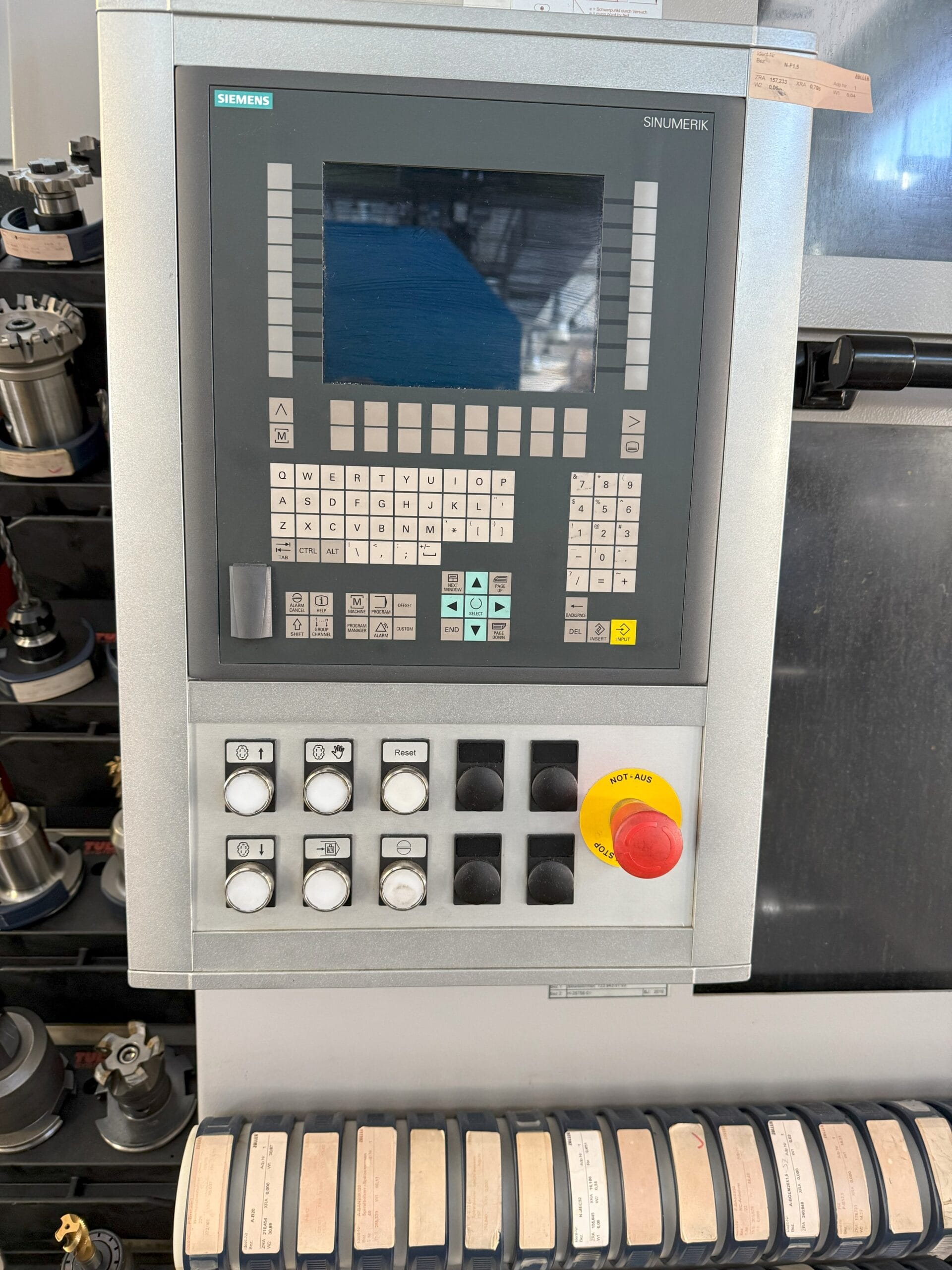
Control:
SIEMENS 840D
Year of construction:
2011
X-way
2000 mm
Y-path
1300 mm
Z-path
1300 mm
Control system
SIEMENS 840D
Condition
Under power
Clamping surface
Ø 1800 mm
Rotary table speeds
0-250 rpm
Tool holder
SK 50
Tool changer places
90 pcs.
Drive power – milling spindle
26 kW
Drive motor speed
22-6000 1/min
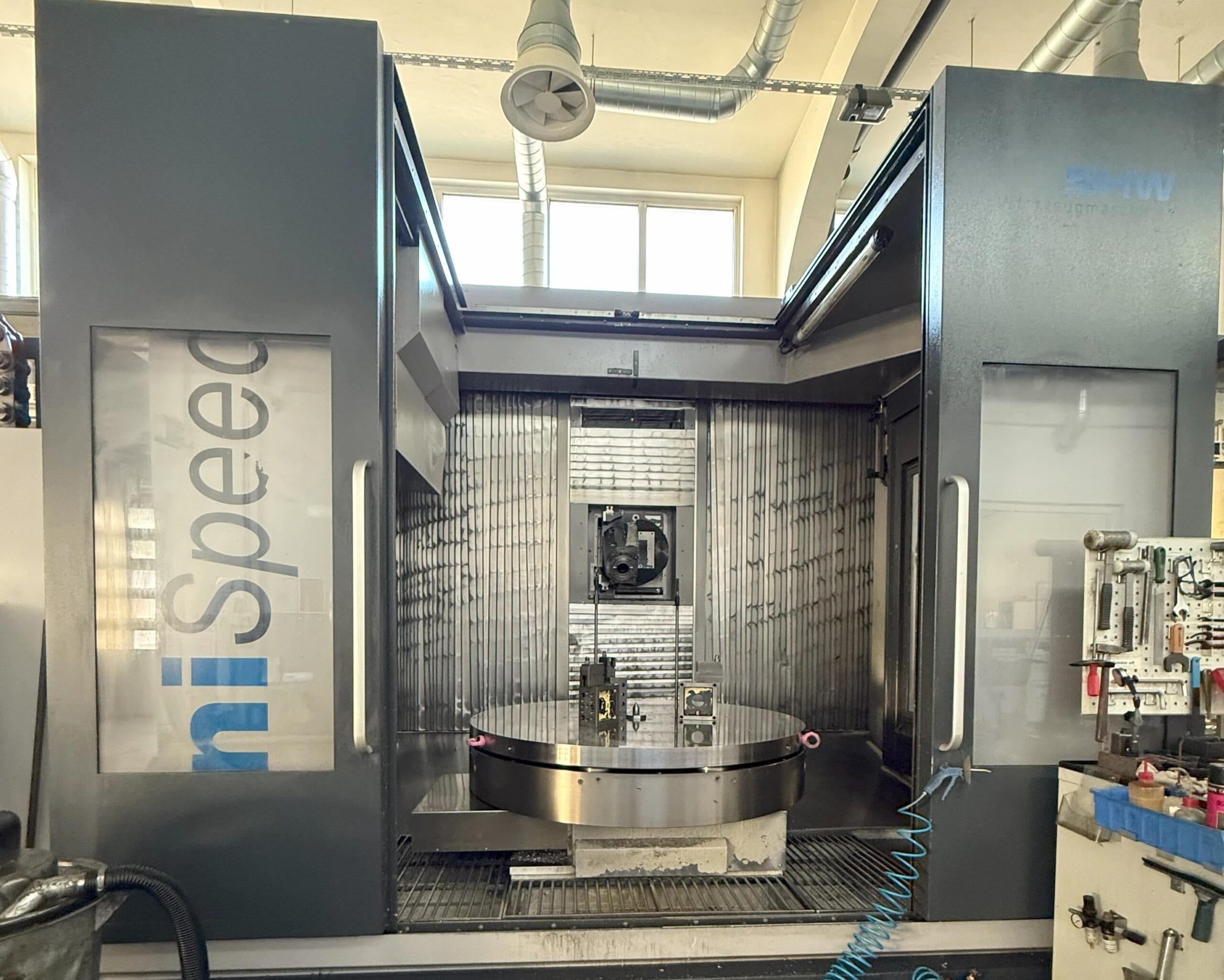
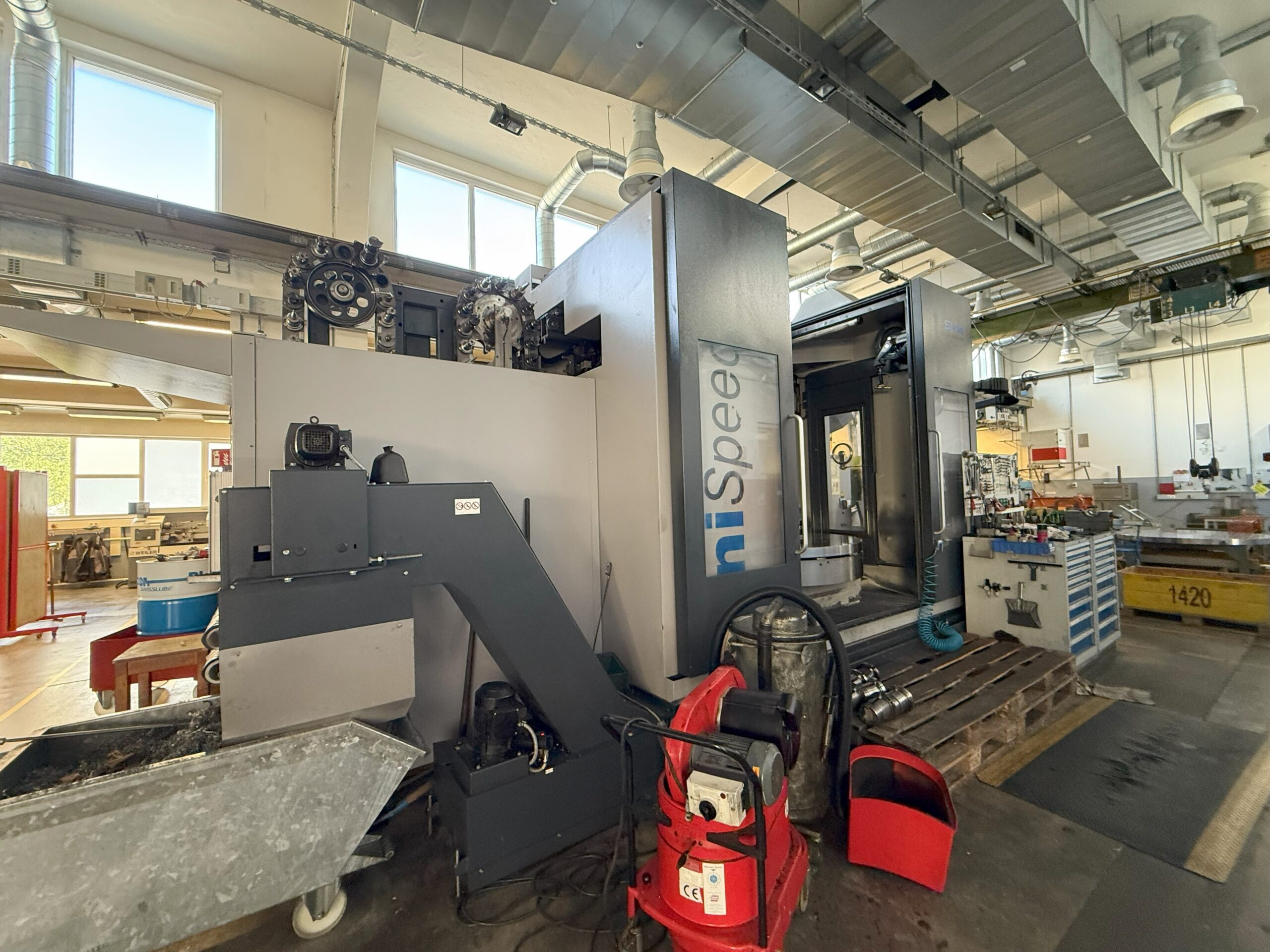
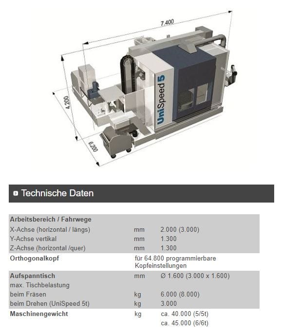
USED UNIVERSAL MILLING/TURNING CENTER SHW-UniSpeed 5T
Year of construction 2011
TRAVEL PATHS OF THE BASIC MACHINE
Machine stand horizontal-longitudinal X = 2,000 mm
Headstock slide vertical Y = 1,300 mm
Headstock horizontal-transverse Z = 1,300 mm
MACHINE FRAME X-AXIS
Intrinsically rigid design as the basis for dynamic and vibration-damped movement of the machine column in the X-axis. No complex foundations are required. The machine column is attached to the machine frame in a portal design. Three hardened compact roller guides ensure maximum precision during movement.
MACHINE STAND Y-AXIS
Stand made of welded steel construction with compact roller guides. Two hardened compact roller guides guarantee the transmission of high cutting performance with consistent quality. The column is protected from chips and cooling water by covers.
HEADSTOCK SLIDE AND HEADSTOCK Z-AXIS
Cast construction made of GGG 60 with hydraulic weight compensation, guided on the machine column with 2 hardened compact roller guides. Headstock also made of GGG 60 cast iron with two opposing compact roller guides.
DRIVE SYSTEM
Digital individual feed drives for contour-accurate work via AC motors with constant torque, feed and rapid traverse range infinitely variable from: X + Y + Z – axis 2-30,000 mm/min, acceleration values in all axes 2 m/s2
MEASUREMENT SYSTEM
Direct non-contact measurement via linear measuring systems for high-precision machining.
AUTOMATIC UNIVERSAL MILLING HEAD IN ORTHOGONAL DESIGN
– Cast construction made of GGG 60
– Milling head holder, automatically swivels 360 x 1 degree
– Milling head, automatically swivels 180 x 1 degree
– 64,800 full-degree positions can therefore not only be realized via the CNC control
are approached, but are programmed and processed.
– Indexing via face gearing
– Tool holder SK 50 DIN 69871
– The milling spindle is equipped with a hydromechanical quick tool clamping system
– Tool pull-in force: 20 kN
– The main drive power is provided by a frequency-controlled, liquid-cooled
AC motor with 26 kW at 100 % ED or 36 kW at 40 % ED
– Speed range 22- 6,000 1/min according to diagram E741.0417.182
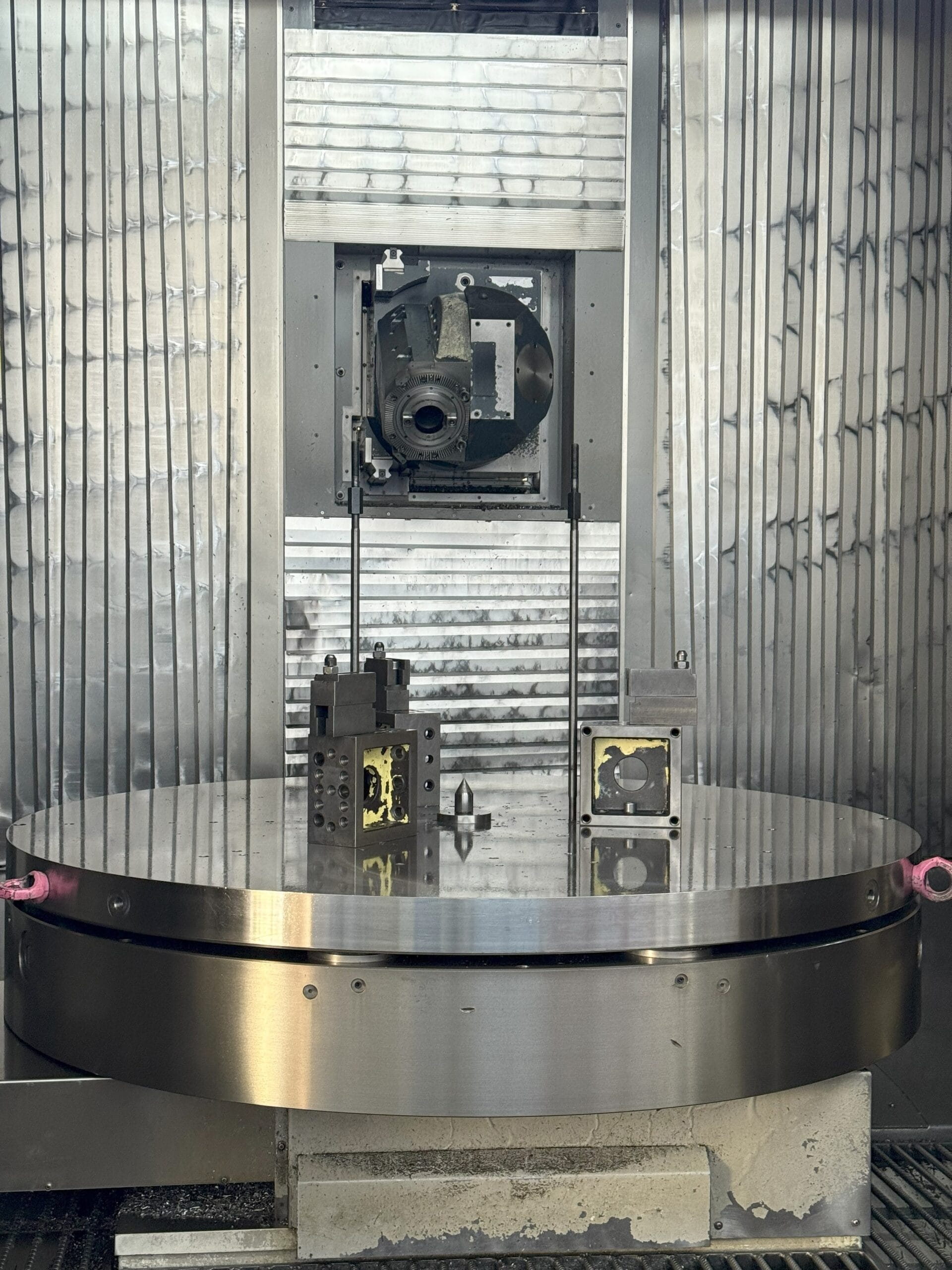
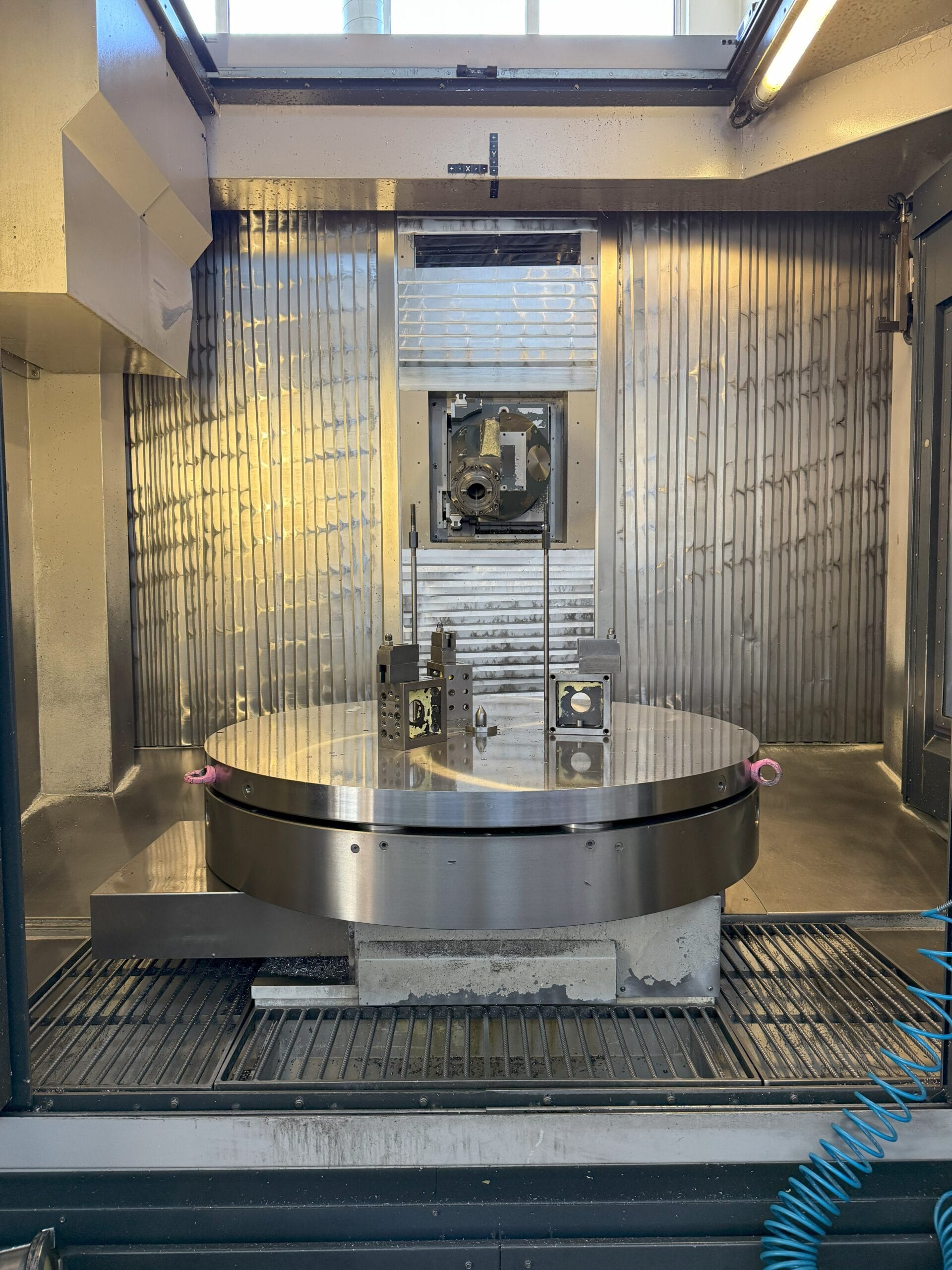
MOTOR-DRIVEN CNC BUILT-IN TURNING/MILLING TABLE
– Axial run-out accuracy at ø 1000 mm 0.015
– Mechanical part accuracy over
direct measuring system sec ± 4
– Speed round part work max. 1/min 5
– Rotating speed max. 1/min 250
– Torque Nm 2,700
(according to speed performance diagram TK 540-192-025)
– Table load during milling (centric) max. kg 6,000
– Table load when turning kg 3,000
– Max. vibration diameter of the workpiece mm 1,800
INTEGRATED WHEEL BALANCER
A special vibration sensor, which is permanently installed in the lower part of the rotary table, detects the vibrations that occur. The associated balancing electronics then suggest the necessary counterweight to the operator at a certain number of degrees and in the diameter of the table. If necessary, the operator can change the suggested parameters according to the conditions on the balancing electronics and have new calculations made.
Operation is via the 840 D control unit.
Balancing quality according to DIN ISO 1940 for machine tool parts and tools: G 6.3. Accessibility on the machine depending on effort >G 3.
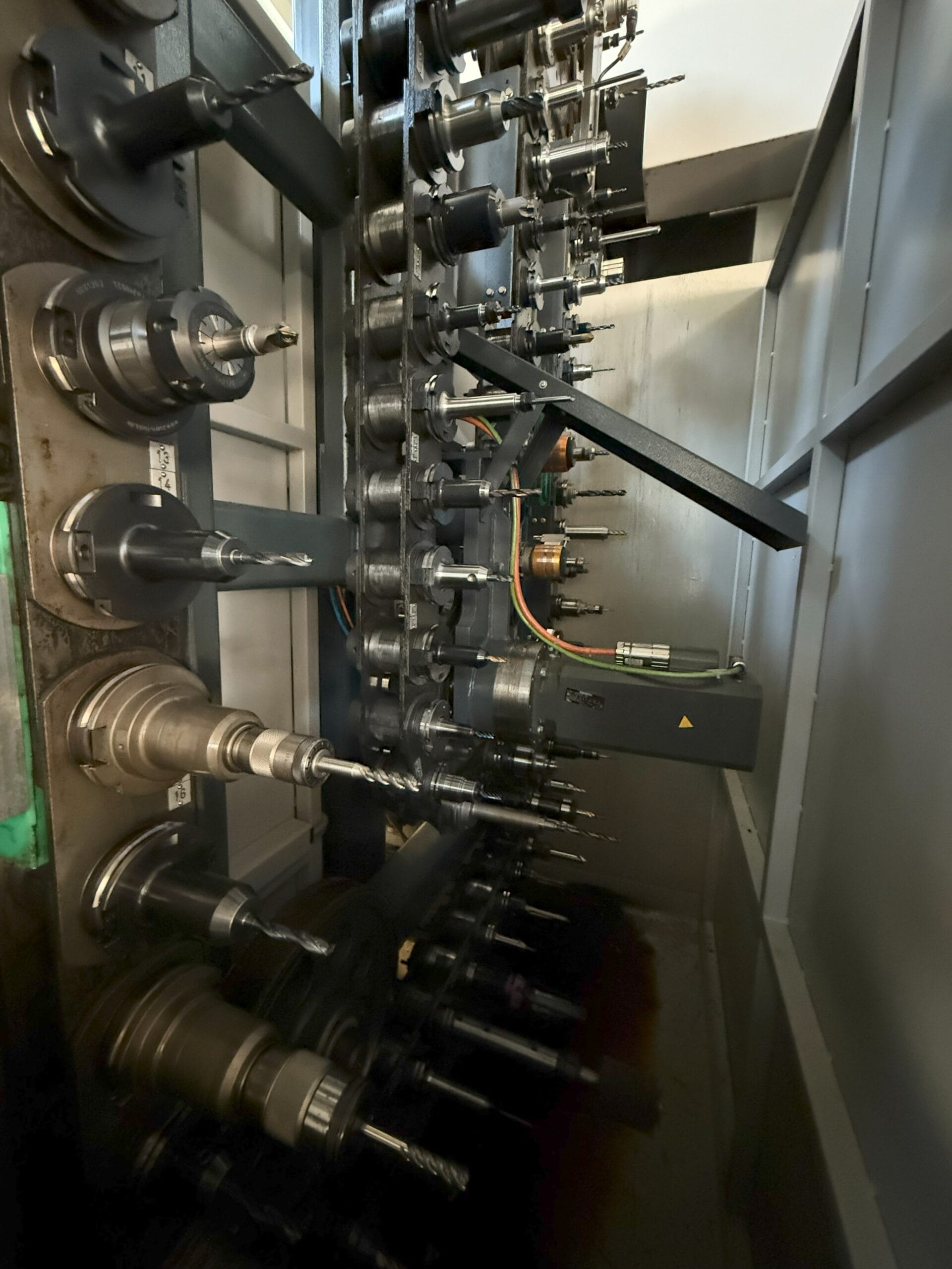
AUTOMATIC TOOL CHANGER
Number of tools in chain magazine 90
Max. Tool diameter with filled magazine mm 125
Max. Tool diameter with free neighboring spaces mm 250
Max. Tool length mm 400
Max. Tool weight kg 25
Max. Tool load torque Nm 40
Tool holder SK 50
Horizontal spindle position for tool change
Fairground coding
Protection against contamination of the spindle taper is provided by blowing out air with each tool change.
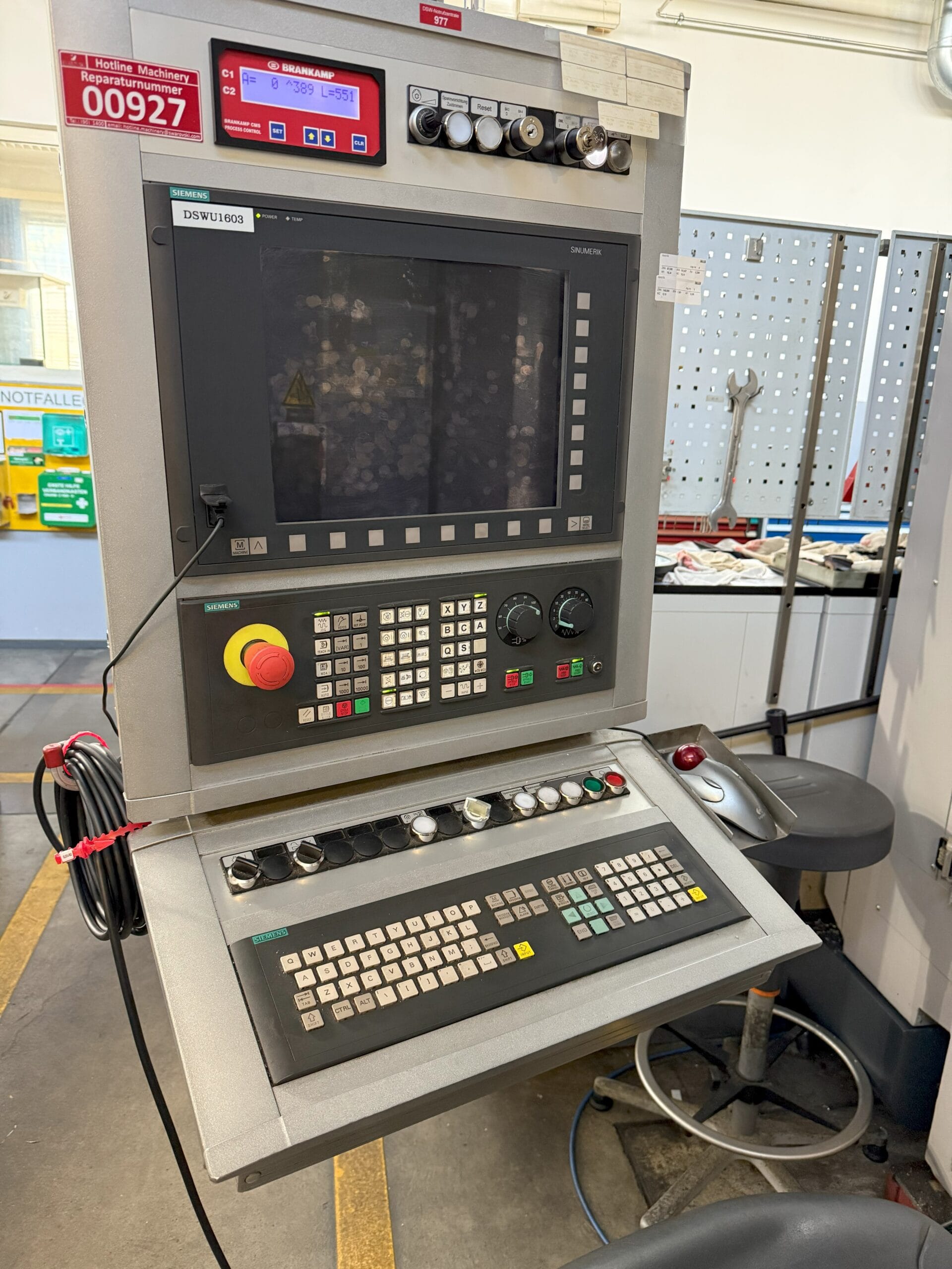
CONTROL
CNC control Siemens 840D
CNC control swivels, attached to the side of the machine.
ELECTRICAL EQUIPMENT
The electrical equipment complies with EN 60204, VBG 4 for 400/230 V (± 10 %) 3 phases, 50 HZ, 160 A slow-blow fuse protection.
Control voltage 24 V, total connected load approx. 80 kVA, 115 A.
The separate control cabinet contains the control units for the main spindle and feed motors as well as the freely programmable adjustment control and the switchgear for the additional units. Protection class of the control cabinet, the feed motors and the main motor IP 54.
The machine and control cabinet are connected to each other via plug connections.
COOLANT SYSTEM
Coolant device for the coolant supply, optionally switchable from external coolant supply (shower ring) to internal coolant supply (IKZ), DIN69871-AD, incl. compact filter system and double switching filter for cleaning the coolant. Infinitely variable pressure and volume control via potentiometer in the control panel.
Pump capacity: 20 l/min at max. 40 bar
Coolant tank: 500 l
COOLING WATER – AIR
Switching the internal or external coolant supply from cooling emulsion to air.
MINIMUM QUANTITY LUBRICATION
(single-channel system)
Minimum quantity lubrication with lubricant supply through the tool spindle. Package consisting of: LUBRIX 850 incl. accessories. The MQL system is adapted to the specific machining conditions by the CNC control system via setting parameters. The oil flow and oil supply are monitored with feedback to the machine.
It is recommended to coordinate the machining task with Lubrix and the tool supplier.
FRAME FLUSHING
Arranged in the rear area of the machine bed. For automatically flushing the chips into the chip conveyor.
RINSING GUN AT THE WORK AREA
Cooling water supply via a flexible hose.
COLLISION MONITORING SYSTEM 1-CHANNEL
Collision monitoring monitors machine and conditional tool collision
Specification of the collision process limit (channel 1):
The process limit for the 1st channel (collision) can be adapted to the machining process by the machine operator via the control unit on the monitoring system. If lower forces occur during machining, the process limit can be reduced, causing the machine to switch off earlier in the event of a collision, thus minimizing damage.
If the force signal exceeds the process limit, the machine is switched off and all axes are braked with maximum torque.
OPERATING MODE 3
according to separate description.
LATE SUPPORTERS
Chip conveyor in hinged belt design
For travel distance X = mm 2,000
Feed width: mm 350
Discharge height: mm 1,250
PURGE AIR
For all linear axes of the machine, the
Glass scales are pressurized with sealing air to minimize the residual risk.
of soiling to a minimum.
RADIO MEASURING PROBE
3-dimensional, signal transmission via integrated transmitter.
For automatic changeover from tool changer or manual changeover. Suitable for determining the workpiece position and zero points.
EXTENSION OF THE SWIVEL RANGE
of the milling head by -90° to +110°. The
position of the milling head holder.
(See swivel range positions no. 5-10)
VISIPORT
Transparent turntable mounted on the machine window, guaranteeing a clear view of the work area. Attached to the right-hand window of the machine (operator side)
ROTARY FEEDTHROUGH IN THE ROTARY TABLE
Cable feed to the clamping elements and the insertion
of the clamping elements provided by Swarovski into the rotary table in accordance with the sketches provided to us as per the attachment.
Rotating union with the following channels:
- Release channel for elements
2nd + 3rd channel for voltage monitoring of the 4 inner pots
4th + 5th channel for clamping hydraulics of mounted workpieces (max. 300 bar)
Hydraulic unit is not included in the scope of delivery.
BUTTONS IN THE CONTROL PANEL FOR ZERO POINT CLAMPING SYSTEM
Loosening/clamping incl. monitoring, as well as preparation of the
Rotary union for a central Röhmheld coupling.
SAFETY GLAZING
Thickness 18 mm instead of standard polycarbonate panes for the entire working area.
AIR PURIFICATION SYSTEM
ILT Type Unifil 1 MRV70-4.0
Intended use:
Extraction and filtration of air contaminated by emulsion mist and smoke
Destination: Emulsion mist and smoke with a flash point above 120 degrees
Functional principle:
Filtering separator (mechanical)
Extraction capacity 4200m3/h
Mounted on the control cabinet next to the machine.
Extraction takes place via a pipe that is installed in the ceiling plate of the sliding door
EXTERNAL HANDSET B-MPI
– EMERGENCY STOP button – Key switch with On/Off position
– Two-line numerical display – Override switch with 12 positions
– 20 Assignment button – Electronic handwheel
– 16LEDs in the – Connection cable
Assignment button
CONTROL CABINET COOLING
Mounted on the enclosure doors. Two-chamber system. There is no exchange of indoor air with outdoor air. The inside air of the enclosure is automatically cooled by an evaporator. At the same time, the inside air of the enclosure is also dehumidified.
LUBRICATION
Guideways: Impulse centralized lubrication
Main spindle: Permanent grease lubrication
Milling head: Oil mist lubrication
ENERGY CONNECTION
Compressed air 4-6 bar (filter pressure regulator with pressure gauge and condensate separator on the machine, connection G ¼)
PAINTING
Machine base color RAL 7004 signal grey.
Headstock unit and tool changer with magazine RAL 7016 anthracite gray.
Chip conveyor, coolant unit and sliding doors RAL 7016 anthracite gray.
Color-neutral standard components RAL 9011 graphite-black.
DD textured paint, silk gloss, oil and soda resistant.
COORDINATE SYSTEM
Y 743.0055
Downloads:

